
VW Touran II 2015-2022 Fuse and Relay Diagram

Volkswagen Touran (5T; 2016-2022) fuses and relays Download
Relay carriers, fuse holders, electronics boxes
⇒ “1.1 Overview of fitting locations - relay carriers, fuse holders, E-boxes”,
⇒ “1.2 Removing and installing electronics box (E-box)”,
⇒ “1.3 Removing and installing relay and fuse holder in electronics box”,
⇒ “1.4 Removing and installing relay and fuse carrier behind dash panel”,
Overview of fitting locations - relay carriers, fuse holders, E-boxes
⇒ “1.1.1 Relay carriers, fuse carriers, electronics box (engine compartment)”,
⇒ “1.1.2 Relay carrier, fuse carrier in dash panel/A-pillar, LHD vehicles”,
⇒ “1.1.3 Relay carrier, fuse carrier in dash panel/A-pillar, RHD vehicles”,
1.1.1 Relay carriers, fuse carriers, electronics box (engine compartment)

1 - Front cover
❑ For electronics box in
engine compartment.
2 - Nut
❑ 9 Nm
3 - Nut
❑ 9 Nm
4 - Electrical wire
❑ For radiator fan ❑ 4.5 Nm
5 - Electrical wire
❑ For terminal 30 ❑ 4.5 Nm
6 - Electrical wire
❑ For electromechanical
power steering ❑ 4.5 Nm
7 - Electrical wire
❑ For battery B+ ❑ 6 Nm
8 - Electrical wire
❑ For terminal 30 ❑ 4.5 Nm
9 - Electrical wire
❑ For alternator ❑ 6 Nm
10 - Fuse holder A - SA-
❑ Removing and installing
11 - Fuse holder
❑ Removing and installing
12 - Cover
❑ For electronics box in engine compartment.
13 - Relay and fuse holder B - SB-
❑ With connecting bar for fuse holder A ❑ Removing and installing
14 - Electrical wire
❑ 6 Nm
15 - Bracket
❑ For engine control unit
16 - Electronics box in engine compartment
❑ Removing and installing
1.1.2 Relay carrier, fuse carrier in dash panel/A-pillar, LHD vehicles

1 - Bracket
❑ For parking aid control unit - J446- / park assist steering control unit - J791-
❑ Removing and installing 2 - Bracket
❑ For onboard supply con‐ trol unit - J519-
❑ Removing and installing
3 - Fuse holder C - SC-
❑ Removing and installing
4 - Bolt ❑ 3 Nm
1.1.3 Relay carrier, fuse carrier in dash panel/A-pillar, RHD vehicles

1 - Bracket
❑ For onboard supply con‐
trol unit - J519-
❑ Removing and installing
2 - Fuse holder C - SC-
❑ Removing and installing
3 - Bolts
❑ Qty. 2 ❑ 3 Nm
1.2 Removing and installing electronics box (E-box)
Special tools and workshop equipment required
♦ Torque wrench - V.A.G 1410-

Removing
– With ignition switched off, disconnect earth cable from battery
Diesel engine
– Remove engine control unit and lay to one side with connec‐
tors attached ⇒ Rep. gr. 23 ; Engine control unit; Removing
and installing engine control unit - J623- .
Petrol engine
– Remove engine control unit and lay to one side with connec‐
tors attached ⇒ Rep. gr. 24 ; Engine control unit; Removing
and installing engine control unit - J623- .
Continued for all vehicles
– Press release buttons -arrows-.
– Remove cover -1-.
– Using screwdriver, release retaining tab -2-.
– Pull off cover -1- in direction of -arrow-.
– Cut through cable tie (bottom) on wiring harness.
– Release fasteners -1, 2, 4- -arrow-.
– Remove fuse holder B -3-, and lay it to one side.

– Unscrew nuts -arrows-.
– Remove bracket for engine control unit -1-.
– Release retaining tab -3-.
– Detach electronics box in engine compartment -2- from studs.
– Lift out engine compartment electronics box -2-.
Installing
Install in the reverse order of removal, observing the following:
Torque settings
1.3 Removing and installing relay and fuse holder in electronics box
1.3.1 Removing and installing fuse holder B - SB

Removing
– With ignition switched off, disconnect earth cable from battery
– Press release buttons -arrow-.
– Remove cover -1-.
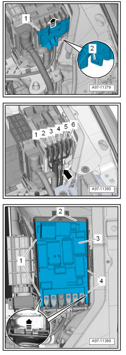
– Using screwdriver, release retaining tab -2-.
– Pull off front cover -1- in direction of -arrow-.
– Mark allocation of electrical wiring at threaded connections for reinstallation.
– Unscrew nuts -1, 2, 4, 5, 6-.
– Unscrew bolt -3-.
– Lay aside electrical wiring -arrow-.
– Cut through cable tie (bottom) on wiring harness.
– Release fasteners -1, 2, 4- -arrow-.
– Remove fuse holder B -3-, and lay it to one side.
Installing
Install in the reverse order of removal, observing the following:
– Fit and secure electrical wiring to fuse holder A according to
markings made earlier.
Torque settings
♦ ⇒ “1.1 Overview of fitting locations - relay carriers, fuse hold‐
ers, E-boxes”
1.3.2 Removing and installing fuse holder A - SA
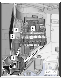
– Remove securing bar -4- upwards from fuse holder B -3-.
– Release retaining tab -1- in direction of -arrow-.
– Remove fuse holder A -2- downwards from fuse holder B -3-.
Installing
Install in reverse order of removal.
1.4.1 Removing and installing relay and fuse carrier behind dash panel, LHD vehicles

Removing
– With ignition switched off, disconnect earth cable from battery
⇒ page 10 .
– Remove dash panel central tube ⇒ General body repairs, in‐
terior; Rep. gr. 70 ; Dash panel central tube; Removing and
installing dash panel central tube .
– Release retaining tab -2- and -4- in direction of -arrows A-.
– Pull out fuse holder C - SC- -3- from bracket -1- in direction of
-arrow B-.
– Disconnect electrical wiring.
Overview of fitting locations - control units, RHD vehicles

1 - Rear lid control unit - J605-
❑ Removing and installing
❑ Removing and installing bracket
2 - Interface for entry and start system - J965-
❑ Overview of fitting loca‐ tions
3 - Onboard supply control unit - J519-
❑ Assembly overview
❑ Removing and installing bracket
4 - Parking aid control unit - J446- or park assist steering control unit - J791-
❑ Assembly overview - parking aid
❑ Assembly overview - park assist steering
❑ Removing and installing bracket
5 - Headlight range control unit - J431- / control unit for corner‐
ing light and headlight range control - J745-
❑ Assembly overview 6 - Diagnostics interface for da‐ ta bus - J533-
❑ Assembly overview

FOR RIGHT HOLDER
Attention! By clicking on the download link you agree, after reading, delete the downloaded file from your computer. All content on the site is taken from free sources and is also distributed free of charge. If you are the author of this material, then please contact us to provide users with a pleasant and convenient alternative after reading the purchase of a quality "original" directly from the publisher. The site administration is not responsible for illegal actions and any damage caused to copyright holders. All materials are posted on the site for information purposes. If you are the copyright holder of the materials posted on this site - contact us.