Audi 80-200 OBD2 Diagnostic Fault Codes. Software Tools

Audi 80-200 car diagnostics, troubleshooting, error codes and their interpretation. Engine, transmission errors. Error codes can be downloaded for free in PDF format
AUDI 80-90 B3 (1986-1991)
Audi 80-90_B3 Service_manual – Fault Memory Ignition – Diagnosis_Fault Memory 20v from 03_90_Download
Audi 80-90_B3 Service_manual – Fault Memory Ignition – Diagnosis_Fault Memory 20v to 03_90_Download
Audi 80-90_B3 Service_manual – Fault Memory Ignition – Diagnosis_Fault Memory 4 cyl_Download
Audi 80-90_B3 Service_manual – Fault Memory Ignition – Diagnosis_Fault Memory 5 cyl_Download
Audi 80-90_B3 Service_manual – Fault Memory Ignition – Ignition_System 4 and 5 cyl_Download
Audi 80-90_B3 Service_manual – Fault Memory Ignition – Ignition_System_20v from 03_90_Download
Audi 80-90_B3 Service_manual – Fault Memory Ignition – Ignition_System_20v to 03_90_Download
AUDI 100 200 SELF-DIAGNOSIS
Audi 100_C4 Automatic_gearbox 01N Self-diagnosis_Download
Audi 100_C4 Automatic_gearbox 018 Self-diagnosis_Download
Audi 100_C4 Automatic_gearbox 097 Self-diagnosis_Download
Audi 100_C4 Running_gear, Self-diagnosis_Download
Audi 100_200 Diagnosis_Fault Memory_Download
Audi 100_200 Diagnosis_Fault Memory (Engine_Code NF with_CIS-E III)_Download
Audi 100_200 Diagnosis_Fault Memory (Engine Code 3B)_Download
Audi 100_200 On-Board_Diagnostic (OBD)_Download
Audi 100_200 Diagnosis_Fault Memory (Troubleshooting)_Download
Access to on-board diagnostic codes
Press and hold the “recycle” button. Then press the manual up arrow to control the flow of data. You should see 1c. Press the temperature (“+”) or down (“-“) buttons to select the code number. Then press the “recycle” button again. The value should be displayed. Press the temperature or down buttons again to display another code.
PLEASE NOTE: Air Flow Motor (V 71) and Potentiometer (G 113) are not installed in US / CANADA vehicles. Ignore values displayed for these components
Diagnostic codes on the climate
on channel 01
00.0 No fault
02.1-02.4 Temperature sensor in the ceiling
03.1-03.4 Temperature sensor in the dashboard
04.1-04.4 Outdoor air intake temperature sensor.
05.1-05.4 Temperature sensor on the front of the machine
06.1-06.4 (ECT) Engine coolant temperature sensor
07.1-07.4 Thermistor for turning on the engine cooling fan
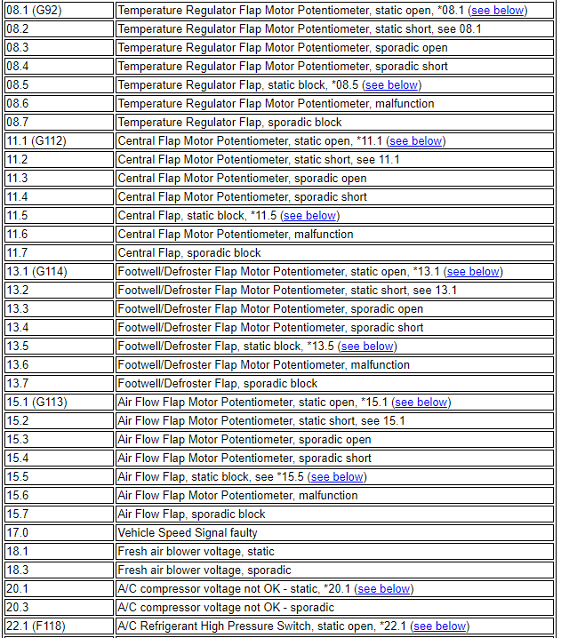
08.1-08.7 (1) Damper control potentiometer
11-1-11.7 (1) Center damper control potentiometer
13.1-13.7 (1) Foot flap control potentiometer
15.1-15.7 Air damper control potentiometer
17.0 Speed sensor
18.1-18.3 Outside air fan (Incorrect voltage)
20.1-20.3 (2) Compressor clutch (Wrong voltage)
22.1-22.5 (3) Coolant high pressure valve
29.1-29.4 Compressor belt slip
(1) – The drive cannot be controlled automatically.
(2) – Residual operation of the compressor clutch until the voltage is greater than 10.8 V for 25 seconds.
(3) – Residual operation of the clutch until the valve closes.
TABLE OF DIAGNOSIS CHANNELS
Channel Function
1 Fault in the system, displayed as a fault code
2 Digital value of the temperature sensor in the cabin (plafond)
3 Digital value of the temperature sensor in the cabin (torpedo)
4 Numerical value of the outdoor air inlet temperature sensor
5 External temperature sensor digital value (front panel)
6 Digital value of the external temperature sensor
7 Digital value of the ambient air temperature sensor in the outdoor air intake fan
8 Digital value of thermostatic damper motor potentiometer
9 Triangular value of thermostatic damper
10 Uncorrected thermostat damper setpoint
11 Digital value of the central damper motor potentiometer
12 Central damper setpoint
13 Digital value of foot flap motor potentiometer
14 Foot flap set value
15 Digital value of air damper motor potentiometer
16 Air flow damper set value
17 Vehicle speed (km/h)
18 Actual voltage of the outdoor air intake fan
19 Specified outdoor air intake fan voltage
20 Compressor clutch voltage
21 Number of step down voltage (non-transient)
22 Compressor refrigerant high pressure valve status
23 Compressor refrigerant high pressure valve cycling
24 Cyclic operation of valves – switches
25 Downshift mechanism (A/D value)
26 Engine Coolant Temperature (ECT) (Sensor Warning Analog / Digital Value)
27 Programming values
28 Engine speed (rpm)
29 Compressor clutch speed (rpm) (equals engine speed x 1.28)
30 Software version
31 Test segments of the display (all segments of the air conditioner control panel light up)
32 Thermostat damper potentiometer failure counter
33 Center damper potentiometer failure counter
34 Foot flap potentiometer failure counter
35 Air flow damper potentiometer failure counter
36 Thermostat damper motor potentiometer feedback value (cold side travel limiter)
37 Thermostat damper motor potentiometer feedback value (hot travel limiter)
38 Feedback value of damper motor potentiometer (cold side travel limiter)
39 Damper motor potentiometer feedback value (hot end limiter)
40 Feedback value of the foot flap motor potentiometer (cold travel limiter)
41 Foot flap motor potentiometer feedback value (hot side limiter)
42 Feedback value of the damper motor potentiometer (cold side travel limiter)
43 Feedback value of damper motor potentiometer (hot side limiter)
44 Duty cycle counter
45 Estimated internal temperature in figures (internal software)
46 Outside temperature, filtered for regulation
(internal software)
47 Outside temperature, unfiltered in degrees .C
(internal software)
48 Outside temperature, unfiltered in numbers
49 Fault counter for speedometer signal (vehicle speed)
50 Simple (in protocol)
51 Engine coolant temperature (ECT) in degrees .C
52 (1) Graphic channel number 1 to 88.8
53 (1) Graphic channel number 1 to 88.8
54 Control characteristics
55 Ambient temperature in (.F or .C) depending on the installation of the air conditioner control panel
56 Indications of the temperature sensor in the cabin in degrees (plafond)
57 Indications of the temperature sensor in the cabin in degrees (torpedo)
58 Readings of the temperature sensor in the duct in degrees
59 Front temperature sensor reading in degrees
60 Readings of the ambient air temperature sensor in the air intake of the outdoor fan in degrees
61 Software (latest) version
Changing Degree Temperature Display

Fault code