
Volkswagen Golf V 2003—2009 Workshop manual. Wiring diagrams

A collection of manuals in English for the maintenance and repair of Volkswagen Golf since 2004 and Volkswagen Golf Plus since 2005. Wiring diagram, Error codes, Diagnostics, Engine and Transmission repair, Oil change and other fluids. Fuses and Relays
Running gear, axles, steering Golf 2004 Golf Plus 2005 Workshop Manual Download
Body Repairs Golf 2004+ Service Manual Download
Maintenance Golf 2004 Golf Plus 2005 Service Manual Download
General body repairs, interior Golf 2004-2009 Workshop Manual Download
General body repairs, exterior Golf 2004 Workshop Manual Download
Maintenance Golf Plus 2005 Service Manual Download
VW Golf Mk5 Touran Golf Plus 2003-2005 Repair Manual Download
Volkswagen Golf 5: Front suspension, servicing Download
Volkswagen Golf 5: Front axle, tightening torques Download
Volkswagen Golf 5: Subframe, stabilizer bar, control arms Download
Volkswagen Golf 5: Wheel bearing, assembly overview Download
Volkswagen Golf 5: Suspension, assembly overview Download
Volkswagen Golf 5: Drive axle, servicing Download
Volkswagen Golf 5: Rear suspension, servicing Download
Volkswagen Golf 5: Rear axle, tightening torques Download
Volkswagen Golf 5: Subframe, transverse link, tie rod, assembly overview Download
Volkswagen Golf 5: Wheel bearing housing, trailing link Download
Volkswagen Golf 5: Shock absorber, coil spring Download
Volkswagen Golf 5: Stabilizer bar, assembly overview Download
VW Golf Mk5 (2004-2008) fuse (panel) box diagram explained
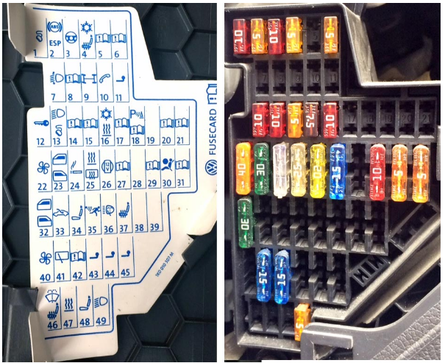
VW Golf Mk5, GTI (2004-2008) fuse (panel) box diagram explained Download
Vehicle wiring diagrams for VW Golf release from November 2003
Due to the large volume, it is not possible to give all the schematic diagrams of models from different years. However, you can use the above diagrams, even if your car is of a different year of manufacture, because the changes, as a rule, concern only particulars.
Wiring designation
- A Battery
- V Starter
- C Alternator
- D Ignition switch
- E Manual switch
- F Mechanical switch
- G Sensor, control device
- H Horn, double tone horn, fanfare horn
- J Relay, control unit
- K, L, M, W, X Signal lights, lamps, lanterns
- N Solenoid valves, resistors, switches
- O Ignition Distributor
- P, Q Spark plug tips, spark plugs
- R Radio
- S Fuses
- T Plug connections
- V Electric motors

1 - relay block. Shown as a gray rectangle. Symbolizes positive connections
2 - an indication of the continuation of the connection to another part. J362 = Anti-theft relay. T6/2 = 6-pin male connector, pin 2
3 - internal connection (thin line). This connection exists inside the part and is not wired.
4 - switching designation. The open side of the patch icon indicates that the node is connected to another circuit
5 - wire cross-section in mm2, e.g. 0.5 = 0.5 mm2
6 - electrical circuit with wire laying. All switches and contacts are shown in mechanical rest
7 - plug connections. T4 = 4-pin plug, /4 = pin 4
8 - node designation. G39 lambda probe with heater
9 - part designation. N80 = solenoid valve 1. The legend below the diagram shows the name of the part
10 - current path number
11 - (-) car
12 - arrow. Indicates the continuation of the diagram on the next page
13 - screws on the relay board. The white circle indicates that this connection is collapsible
14 - relay location number. Indicates the location of the relay on or at the relay box
15 - link to connect the line with another node. The number in the rectangle indicates which path the wire is connected to. In this case, to 114
16 - connection in the wiring harness. Non-separable connection
17 - connection terminal In this case, terminal 30, 45-pin plug, pin 21
18 - fuse. S28 = fuse #28 15 amps
19 - an indication that the wire is connected to the final part of the wiring diagram. The letter indicates where the wire is located in the following diagram.
20 - connection point to (-). The legend provides data on the location of the point (-) on the vehicle
Battery, terminals 30 and 15 of the power relay, on-board switching relay, fuses:

A battery
With generator
J317 terminal 30 power relay
J329 terminal 15 power relay
J519 Onboard electrical switching relay
SA1 fuse 1 in the fuse box above the battery
SA6 fuse 6 in the fuse box above the battery
SB4 fuse 4 in the fuse box
SB5 fuse 5 in fuse box
SB16 fuse 16 in the fuse box
SB17 fuse 17 in the fuse box
SB24 fuse 24 in fuse box
SB31 fuse 31 in the fuse box
SB38 fuse 38 in fuse box
SB40 fuse 40 in fuse box
SB47 fuse 47 in the fuse box
SB48 fuse 48 in fuse box
SB49 fuse 49 in the fuse box
T40 40-pin plug 507 screw connection (30) on the fuse box above the battery
Onboard electrical system switching relay, fuses:

J519 Onboard electrical switching relay
SC1 fuse 1 in fuse box
SC4 fuse 4 in the fuse box
SC6 fuse 6 in the fuse box
SC13 fuse 13 in fuse box
SC14 fuse 14 in fuse box
SC15 fuse 15 in fuse box
SC16 fuse 16 in fuse box
SCI7 fuse 17 in fuse box
SC31 fuse 31 in the fuse box
SC40 fuse 40 in fuse box
SC41 fuse 41 in the fuse box
SC42 fuse 42 in the fuse box
SC49 fuse 49 in the fuse box
B162 terminal 75a in the interior wiring harness
B163 Positive potential connection 1 (terminal 15) in passenger compartment wiring harness
B169 Positive potential connection 1 (terminal 30) in passenger compartment wiring harness
Left headlight, left fog lamp, right fog lamp, onboard electrical switching relay, fuses:

J519 Onboard electrical switching relay
L22 left fog light bulb
L23 right fog light bulb
M1 left parking light bulb
M5 front left turn signal bulb
M29 left dipped beam headlight bulb
M30 left high beam headlight bulb
SC24 fuse 24 in fuse box
SC25 fuse 25 in fuse box
SC26 fuse 26 in the fuse box
SC46 fuse 46 in the fuse box
T5n 5-pin plug, in the front of the engine compartment on the left
V48 headlight range control motor
203 ground connection (-) in the fog lamp wiring harness
376 ground connection (-) 11 in the main wiring harness
655 ground point (-) on the left headlight
A84 terminal 58L in the wiring harness on the instrument panel
A181 Connection 2 positive potential (left turn signal) in the instrument panel wiring harness
B135 connection 1 (terminal 15a) in the interior wiring harness
B162 connection (terminal 75a) in the passenger compartment wiring harness
B338 connection 1 (terminal 56) in the main wiring harness
B457 connection 1 (potentiometer) in the main wiring harness
B456 connection (terminal 56b) in the main wiring harness
B458 connection 2 (potentiometer) in the main wiring harness
Right headlight, dimmer, switch illumination, instrument panel, headlight hydrocorrector, switch illumination:

Right marker, Left marker, Left fog light bulb, Right reversing light bulb:

Light switch, fog light switch, rear fog light switch, light switch illumination bulb:

Auxiliary brake light bulb, license plate light, turn signal light in the rearview mirror on the driver's side, turn signal light on the passenger side:

Steering column adjustment relay, wiper switch, wiper interval switch, wiper interval relay:

Cruise control switch, X terminal unloader relay, steering angle relay, steering angle sensor:

Ignition switch, steering column tilt relay, turn signal switch, ignition key lock relay, horn:

Hood contact switch, rain and light sensor, dual washer pump relay 2, windshield wiper motor, washer jets:

F266 hood contact switch
G397 rain and light sensor
J400 Wiper Motor Relay
J519 Onboard electrical switching relay
J730 dual washer pump relay 2
T2n 2-pin plug to the right of the upper bulkhead near the headlight
T3ae 3-pin plug
T4q 4-pin plug
V glass cleaner motor
Z20 left washer jet heater
Z21 right washer jet heater
373 ground connection (-) 8 in the main wiring harness
A36 connection (terminal 75a) in the wiring harness on the instrument panel
B465 connection 1 in the main wiring harness
B528 connection 1 in the main wiring harness (light guide)
Windshield wiper motor, washer pump, rear window defroster, dual washer pump relay 1. rear window defroster relay, high-pitched horn:

M2 high tone horn
J9 rear defroster relay
J519 Onboard electrical switching relay
J729 Dual washer pump relay 1
T4u 4-pin plug
T5a Black 5-pin plug on rear left fender
T5e Pink 5-pin plug on rear left fender
V12 rear window wiper motor
V59 washer pump front and rear windows
Z1 rear window defroster
663 point "mass" (-) on the rear right wing
A90 connection of a sound signal in a plait of wires on the panel of devices
B183 Washer pump connection 1 in passenger compartment wiring harness
B184 washer pump connection 2 in passenger compartment wiring harness
Cigarette lighter, 12 V socket, rear cigarette lighter, driver's vanity mirror lighting, front passenger's vanity mirror lighting:

Instrument panel, anti-theft sensing coil, parking brake warning light sensor, brake fluid level sensor:

D2 anti-theft reading coil
F9 parking brake warning light sensor
F34 brake fluid level sensor
J285 instrument panel relay
J362 anti-theft relay
J519 Onboard electrical switching relay
To instrument panel
K115 anti-theft warning light
K118 brake warning light
T2x 2-pin plug
T36 36-pin plug
367 connection to (-) 2 in the main wiring harness
376 connection to (-) 11 in the main wiring harness
381 connection to (-) 16 in the main wiring harness
602 dots (-) in the footwell on the left side
655 dot (-) on the left headlight
B277 connection 1 positive (terminal 15a) in the main wiring harness
B380 connection 2 (brake pad wear warning light) in the main wiring harness
Instrument panel, engine oil pressure sensor, ambient air temperature sensor, coolant temperature gauge sensor, washer fluid level sensor, left front brake pad wear sensor:

Instrument panel, on-board electrical switching relay, warning lights, outside temperature sensor:

Instrument panel, diagnostic connector, warning lights:

Switching relay of the onboard electrical system, diagnostic socket:

J... engine control units
J519 Onboard electrical switching relay
J533 diagnostic connector
R radio
T12b 12-pin plug on the left side of the fairing box
T16 16-pin diagnostic connector on the instrument panel on the left
T16b 16-pin plug
T20 20-pin plug
385 ground connection (-) 20 in the main wiring harness
A76 line K self-diagnosis system
A178 data bus connection for passenger compartment devices (High) in the instrument panel wiring harness
A179 passenger compartment data bus connection (Low) in instrument panel wiring harness
B383 Connection 1 of the switching bus of the power plant and chassis control units (High) in the main wiring harness
B390 Connection 1 of the switching bus of the power plant and chassis control units (Low) in the main wiring harness
B397 Convenience signal switching bus connection 1 (High) in the main wiring harness
B406 Convenience signal switching bus connection 1 (Low) in the main wiring harness
VW Golf 1K1, engine starts but immediately stalls, event 17978, 18048 in the engine control unit
The following events are logged in the engine control unit:
17978 P1570, the engine control unit is blocked
18048 P1640, the control unit is defective
Additionally, the following event was registered in the immobilizer control unit:
02241, engine control unit, immobilizer data not adapted
Solution in terms of service
Readjust the control unit and, if necessary, update the engine control unit
Re-adapt the engine control unit to the immobilizer using ⇒ Guided Fault Finding.
