
Volkswagen Golf 2015, Golf Variant, GTI, Repair Manual. Wiring diagram

A collection of manuals in English for the maintenance and repair of Volkswagen Golf mk7 /Golf GTI/Golf Variant since 2013. This guide will help you fix your Golf yourself or find it broken. Here you will find color wiring diagrams and error codes. List of fuses and relays
GTI 2014 Repair Manual Generic Scan Tool Download
Repair Manual Golf 2015, Variant 2015 Body Exterior Download
Repair Manual Golf 2015 Variant 2015 Body Interior Download
Golf 2015 Variant 2015 Direct Shift Gearbox Repair Manual Download
Golf 2015 Variant 2015 Manual Transmission Download
Repair Manual Heating, Ventilation and Air Conditioning Download
Repair Manual Golf 2015 Golf Variant 2015 Manual Transmission Download
Repair Manual Golf 2015 Golf Variant 2015 Automatic Transmission Download
Repair Manual Engine Mechanical, Fuel Injection and Ignition Download
Repair Manual Fuel Supply - Gasoline Engines Download
Repair Manual Golf 2015 Golf Variant 2015 Brake System Download
Repair Manual Golf 2015 Golf Variant Suspension, Wheels, Steering Download
Repair Manual Golf 2015 Electrical Equipment Download
Communication Repair Manual Golf 2015 Download
Wheel and Tire Guide Repair Manual Golf 2015 Download
Rear Final Drive Repair Manual Golf 2015 Download
7-speed dual clutch gearbox 0CW Workshop Manual Golf 2013 Download
Electrical Equipment Golf Variant 2015 Golf Variant 2015 Download
Fuses and relays Golf mk7 /Golf GTI
Replace blown fuses only with fuses of the same rating (color and marking must be identical) and size.
FUSE TYPES
- Standard flat fuses (ATO®).
- Small flat fuses (MINI®).
- JCASE® fuses.
|
Color |
Current strength, A |
|
|
(ATO®/MINI®) |
(JCASE®) |
|
|
Black |
1 |
--- |
|
Beige |
5 |
--- |
|
Brown |
7.5 |
--- |
|
Red |
10 |
50 |
|
Blue |
15 |
20 |
|
Yellow |
20 |
60 |
|
White or transparent |
25 |
--- |
|
Green |
30 |
40 |
|
Orange |
40 |
--- |
|
Pink |
30 |
30 |
Fuse box in the front panel
Opening the fuse box in the front panel
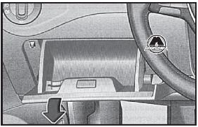
Cover for the fuse box in the front panel: on the left, next to the steering wheel
Open the storage compartment on the driver's side and pull hard on the left side in the direction of the arrow. This may require some effort.
To install, insert the storage compartment into the opening of the front panel and press until it locks into place.
Fuse table in the fuse box in the front panel
The table shows the installation locations of fuses that may be of interest to the customer. The left column indicates the location of the fuse, then the type of fuse, the amperage rating, and the last column indicates the consumer(s) that receives the supply voltage through this fuse.

Location of the fuses in the front panel
|
Nest |
Fuse type |
Current in amperes |
Consumers |
|
F4 |
MINI® |
7.5 |
Infotainment control panel |
|
F7 |
MINI® |
10 |
Air conditioner or heater control panel , heated rear window relay, automatic transmission selector lever |
|
F8 |
MINI® |
10 |
Light switch, rain sensor, electromechanical parking brake |
|
F10 |
MINI® |
10 |
Display |
|
F12 |
ATO® |
20 |
Infotainment system components |
|
F14 |
ATO® |
30 |
Fan controller |
|
F16 |
MINI® |
7.5 |
Telephone |
|
F20 |
MINI® |
15 |
Seat adjustment |
|
F23 |
JCASE® |
40 |
Headlights and outdoor lighting |
|
F24 |
ATO® |
30 |
Panoramic electric tilt/slide sunroof |
|
F26 |
ATO® |
30 |
Heated seats |
|
F28 |
ATO® |
20 |
Trailer control unit (left) |
|
F31 |
JCASE® |
40 |
Headlights and outdoor lighting |
|
F38 |
ATO® |
20 |
Trailer control unit (right) |
|
F40 |
ATO® |
20 |
Cigarette lighter, sockets |
|
F42 |
ATO® |
40 |
windshield washer, headlight washer |
|
F43 |
JCASE® |
30 |
Interior lighting |
|
F44 |
ATO® |
15 |
trailer control unit |
|
F47 |
ATO® |
15 |
Rear window cleaner |
|
F53 |
ATO® |
30 |
Rear window heating |
Note
Depending on the version and equipment of a particular vehicle, there may be some differences from the fuse numbers and their sockets indicated in the table. If necessary, the exact location of the fuses can be obtained from a Volkswagen Dealership.
Automatic fuses can be used in the power supply circuits of power windows and power seats, which automatically turn on again after the cause of the overload (for example, freezing of windows) has been eliminated.
FUSE BOX IN THE ENGINE COMPARTMENT

Engine compartment: fuse box cover (1) with plastic tweezers (2)
1. Open the hood (see Chapter 3, Vehicle Owner's Manual, Vehicle Maintenance section),
2. Push the tabs in the direction of the arrow to unlock the fuse box cover.
3. Remove the cover towards the top.
4. To install, place the cover on the fuse box and press down until it clicks into place on both sides.
Note
- On the inside of the cover there may be plastic tweezers (2) for extracting the fuses.
- Remove and install the fuse box cover with care to prevent damage to vehicle systems.
- Protect exposed fuse boxes from dirt and moisture. Dirt and moisture in the fuse box can damage electrical equipment.
- There are other fuses in the car that are not mentioned in this chapter. They can only be replaced at a service station.
