
VW Touran II 2015-2022 Fuse and Relay Diagram

Volkswagen Touran (5T; 2016-2022) fuses and relays Download
Relay carriers, fuse holders, electronics boxes
⇒ “1.1 Overview of fitting locations - relay carriers, fuse holders, E-boxes”,
⇒ “1.2 Removing and installing electronics box (E-box)”,
⇒ “1.3 Removing and installing relay and fuse holder in electronics box”,
⇒ “1.4 Removing and installing relay and fuse carrier behind dash panel”,
Overview of fitting locations - relay carriers, fuse holders, E-boxes
⇒ “1.1.1 Relay carriers, fuse carriers, electronics box (engine compartment)”,
⇒ “1.1.2 Relay carrier, fuse carrier in dash panel/A-pillar, LHD vehicles”,
⇒ “1.1.3 Relay carrier, fuse carrier in dash panel/A-pillar, RHD vehicles”,
1.1.1 Relay carriers, fuse carriers, electronics box (engine compartment)

1 - Front cover
❑ For electronics box in
engine compartment.
2 - Nut
❑ 9 Nm
3 - Nut
❑ 9 Nm
4 - Electrical wire
❑ For radiator fan ❑ 4.5 Nm
5 - Electrical wire
❑ For terminal 30 ❑ 4.5 Nm
6 - Electrical wire
❑ For electromechanical
power steering ❑ 4.5 Nm
7 - Electrical wire
❑ For battery B+ ❑ 6 Nm
8 - Electrical wire
❑ For terminal 30 ❑ 4.5 Nm
9 - Electrical wire
❑ For alternator ❑ 6 Nm
10 - Fuse holder A - SA-
❑ Removing and installing
11 - Fuse holder
❑ Removing and installing
12 - Cover
❑ For electronics box in engine compartment.
13 - Relay and fuse holder B - SB-
❑ With connecting bar for fuse holder A ❑ Removing and installing
14 - Electrical wire
❑ 6 Nm
15 - Bracket
❑ For engine control unit
16 - Electronics box in engine compartment
❑ Removing and installing
1.1.2 Relay carrier, fuse carrier in dash panel/A-pillar, LHD vehicles

1 - Bracket
❑ For parking aid control unit - J446- / park assist steering control unit - J791-
❑ Removing and installing 2 - Bracket
❑ For onboard supply con‐ trol unit - J519-
❑ Removing and installing
3 - Fuse holder C - SC-
❑ Removing and installing
4 - Bolt ❑ 3 Nm
1.1.3 Relay carrier, fuse carrier in dash panel/A-pillar, RHD vehicles

1 - Bracket
❑ For onboard supply con‐
trol unit - J519-
❑ Removing and installing
2 - Fuse holder C - SC-
❑ Removing and installing
3 - Bolts
❑ Qty. 2 ❑ 3 Nm
1.2 Removing and installing electronics box (E-box)
Special tools and workshop equipment required
♦ Torque wrench - V.A.G 1410-

Removing
– With ignition switched off, disconnect earth cable from battery
Diesel engine
– Remove engine control unit and lay to one side with connec‐
tors attached ⇒ Rep. gr. 23 ; Engine control unit; Removing
and installing engine control unit - J623- .
Petrol engine
– Remove engine control unit and lay to one side with connec‐
tors attached ⇒ Rep. gr. 24 ; Engine control unit; Removing
and installing engine control unit - J623- .
Continued for all vehicles
– Press release buttons -arrows-.
– Remove cover -1-.
– Using screwdriver, release retaining tab -2-.
– Pull off cover -1- in direction of -arrow-.
– Cut through cable tie (bottom) on wiring harness.
– Release fasteners -1, 2, 4- -arrow-.
– Remove fuse holder B -3-, and lay it to one side.

– Unscrew nuts -arrows-.
– Remove bracket for engine control unit -1-.
– Release retaining tab -3-.
– Detach electronics box in engine compartment -2- from studs.
– Lift out engine compartment electronics box -2-.
Installing
Install in the reverse order of removal, observing the following:
Torque settings
1.3 Removing and installing relay and fuse holder in electronics box
1.3.1 Removing and installing fuse holder B - SB

Removing
– With ignition switched off, disconnect earth cable from battery
– Press release buttons -arrow-.
– Remove cover -1-.
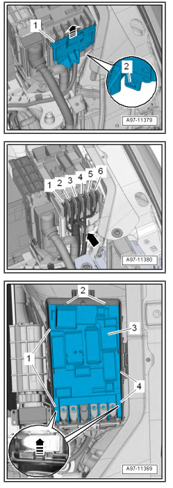
– Using screwdriver, release retaining tab -2-.
– Pull off front cover -1- in direction of -arrow-.
– Mark allocation of electrical wiring at threaded connections for reinstallation.
– Unscrew nuts -1, 2, 4, 5, 6-.
– Unscrew bolt -3-.
– Lay aside electrical wiring -arrow-.
– Cut through cable tie (bottom) on wiring harness.
– Release fasteners -1, 2, 4- -arrow-.
– Remove fuse holder B -3-, and lay it to one side.
Installing
Install in the reverse order of removal, observing the following:
– Fit and secure electrical wiring to fuse holder A according to
markings made earlier.
Torque settings
♦ ⇒ “1.1 Overview of fitting locations - relay carriers, fuse hold‐
ers, E-boxes”
1.3.2 Removing and installing fuse holder A - SA
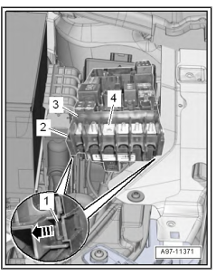
– Remove securing bar -4- upwards from fuse holder B -3-.
– Release retaining tab -1- in direction of -arrow-.
– Remove fuse holder A -2- downwards from fuse holder B -3-.
Installing
Install in reverse order of removal.
1.4.1 Removing and installing relay and fuse carrier behind dash panel, LHD vehicles

Removing
– With ignition switched off, disconnect earth cable from battery
⇒ page 10 .
– Remove dash panel central tube ⇒ General body repairs, in‐
terior; Rep. gr. 70 ; Dash panel central tube; Removing and
installing dash panel central tube .
– Release retaining tab -2- and -4- in direction of -arrows A-.
– Pull out fuse holder C - SC- -3- from bracket -1- in direction of
-arrow B-.
– Disconnect electrical wiring.
Overview of fitting locations - control units, RHD vehicles

1 - Rear lid control unit - J605-
❑ Removing and installing
❑ Removing and installing bracket
2 - Interface for entry and start system - J965-
❑ Overview of fitting loca‐ tions
3 - Onboard supply control unit - J519-
❑ Assembly overview
❑ Removing and installing bracket
4 - Parking aid control unit - J446- or park assist steering control unit - J791-
❑ Assembly overview - parking aid
❑ Assembly overview - park assist steering
❑ Removing and installing bracket
5 - Headlight range control unit - J431- / control unit for corner‐
ing light and headlight range control - J745-
❑ Assembly overview 6 - Diagnostics interface for da‐ ta bus - J533-
❑ Assembly overview
